The system is controlled by the Master colour touch-screen controller mounted in a panel in the Plant Room. A secondary slave colour touch-screen controller would typically be mounted in the Pool House, which displays monitoring and control information for the pool users. Maintenance functions are only available in the Plant Room. Note that the two controllers communicate via an Ethernet IP link, and it is possible to add more than one slave controller to the system. Slave controllers do not even have to be in the same building as the Master controller.
Inside the Plant Room, the system functionally divides into two major sections which are pool management and heat source management.
Pool plant will typically include various pumps and valves used in the filtration processes, and sometimes UV sterilisation or electrolytic chlorination equipment. Heat sources may be electrical, gas or oil-fired boiler, air handling unit, solar, geothermal heat pumps, or any combination of these.
Extra features such as Spa hydrotherapy jets and air blowers can also be controlled. Typically there would be Spa-side switches to operate these, but they can also be controlled from any of the colour touch screen panels. Nearly all pools feature lighting either in or around the pool area, and these too may be controlled by the system.
One feature our clients have found particularly useful is the simple “All Off” button on the colour touch screens, so that when they have finished using the facility one button turns off all lighting and Spa features together.
The system may also be managed via a web-page style interface over the Internet or a phone based app, both of which provides the same set of functions. The major advantage of a web-based interface rather than an App is that it runs correctly on any device with a web browser, without the need for frequent updates. The free management software provides the ability to monitor several controllers or installations simultaneously in real time
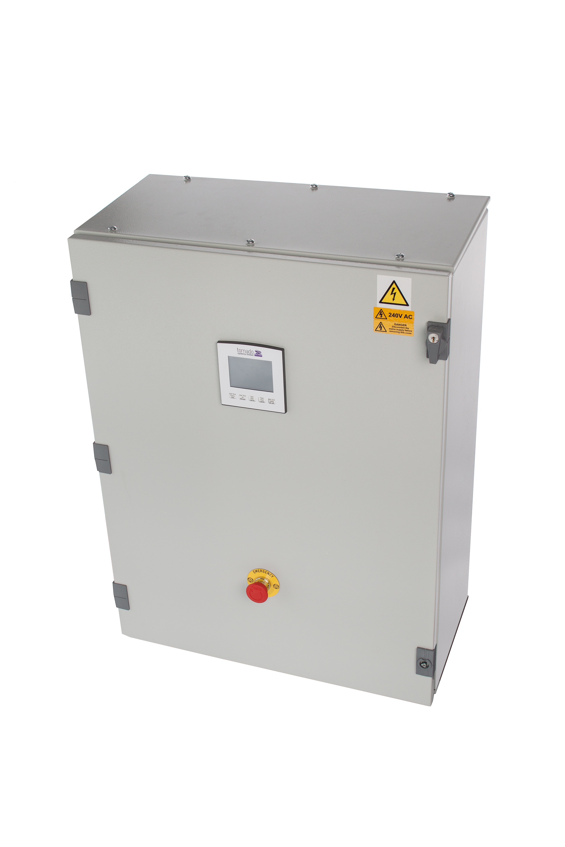
Control Cabinet – External View
A typical controller installation in the Plant Room is shown below. There really is very little to see, due to the design simplicity afforded by the sophisticated controller.
Let’s look at a typical example installation, where pool heating is provided by a very large oil-fired boiler. Safety is paramount in the system design, and this installation includes fire detection for the boiler and Plant Room.
A reassuring “Emergency Panic Button” is fitted inside the Plant Room. When this button is pressed, the Boiler and all pumps are to be shut down, and an alarm signalled. The system can only be reset from the Plant Room for safety reasons.
All electrical supplies to the components of the system are individually protected by Residual Current Circuit Breakers (RCBOs), for absolute safety.
During the winter months an outdoor pool is usually decommissioned (and possibly emptied), so all pool-related functions must be disabled at this time. However, it is still normally vital to provide Frost Protection for the Plant Room and Pool House.
“Pool Decommissioned” status is to be selected or deselected by the maintenance section of the Plant Room Controller menu, which must be preserved across power failures.
Where the heating an installation is provided by a large boiler installation, the boiler will often be fitted with various auxiliary pumps (e.g. Circulation Pump, Shunt Pump) which must be run in the correct sequence when the Boiler is fired. This is often required to make sure no hotspots occur inside which could damage the heat exchanger or cause it to crack due to thermal shock.
The Boiler is protected by a fire sensor placed over the burner, and in the event of a fire, all Boiler Pool House systems are shut down and an alarm signalled.
All individual components of the system are controlled with individual Solid State Relays (SSR), which are silent in operation and contain no moving parts for optimum reliability. Whilst these are state-of-the-art, they are of course somewhat more expensive than old-fashioned electro-mechanical contactors. Extensive diagnostic circuitry is built in to the system so that each individual system component can be monitored for failure, in terms of open or short circuit, or power supply failure.
In this way individual component failures can be identified and reported. This is critical, as individual failures can require other parts of the system to be shut down safely.
Other system parameters are monitored too. For example the boiler is provided with circulation system pressure monitor, and the Boiler (including pumps) must not be operated when the pressure is too low. The pressure monitor signals to the controller that there is insufficient pressure in the system for normal boiler operation.
The Boiler must not be fired unless the circulation and auxiliary pumps are operating correctly, in order to protect it from sudden changes of temperatures that may cause severe damage (i.e. cracking of the cast-iron heat exchanger).
Hot water leaving the boiler feeds a manifold equipped with a series of two-port valves. These valves would allow circulation from the Boiler to the following example systems:
- Pool House heating system (may be radiators and/or under-floor heating).
- Pool House Domestic Hot Water cylinder.
- Main pool heat exchanger.
- Spa pool heat exchanger.
The Controller panel motorises each of these valves as required, and reads the status of each one. Typically these valves take 8-10 seconds to open after power has been applied, so the status must not be read before that time. The Circulation pump and boiler should only be operated after the open status of at least one of the valves is confirmed.
Status of these valves is checked constantly when the boiler is operating, because it is possible for them to fail in service which causes them to close immediately.
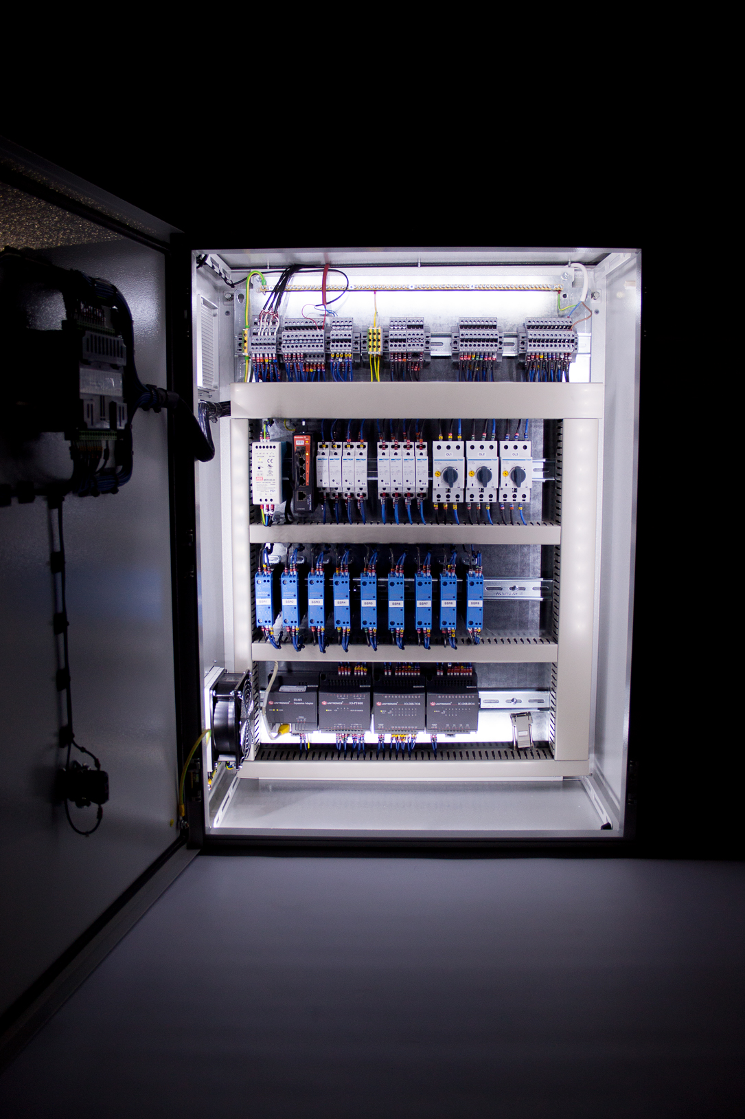
Illuminated Cabinet, for Safety and Convenience in the Darkest Plant Room
The boiler and pumps must not be run unless at least one of the two-port valves is open. If a valve fails to open or closes unexpectedly (and it is the only one open), the boiler must be shut down as soon as possible.
Sensors read the internal temperature of the Pool House, the Plant Room, and the external atmospheric temperatures. The user can program a schedule for operating the Pool House heating times and temperature, or the Domestic Hot Water operating times, from either the Pool House or Plant Room.
These sensors enable frost protection for both the Pool House and Plant Room, and the external temperature may be factored in to the calculation. If the temperature falls too low in the Pool House or the Plant Room (under 5 Degrees Centigrade – programmable), the Pool House heating and Domestic Hot Water should be activated until the temperature is safe again.
The main pool and Spa pool heat exchanger valves must not be opened under the following conditions:
- The pool is decommissioned, since there will be no pool water in the heat exchangers.
- The appropriate filter pump is not running, since there will be no pool water circulating in the heat exchangers.
Note that the operation of the main pool filter and Spa pool filter pumps provides flow through their respective heat exchangers. Water flow in these systems is monitored constantly, so that related systems can be shut down safely. In our example installation, the Pool House Control system also controls the UV Sterilisers and Electrolytic Chlorination unit for each pool.
For instance, if the main pool pump were to fail, it would be necessary to stop boiler circulation into the heat exchanger, and shut off the UV and Chlorination systems for safety. However al other parts of the system can carry on safely. Note that on larger systems sometimes two parallel pumps are provided, so that an alternative is available.
At all other times when the pool is commissioned, the main pool filter and Spa pool filter pumps can be run. The main pool filter and Spa pool filter pumps are switched on or off from the Plant Room only, after the pool status is set as commissioned. The status of pump operation must be preserved across system power failure. In some installations, an Inverter is required for control of pump speed or start-up. Of course this is easily controlled by the system, and can offer energy savings and longevity for the pumps.
When the Boiler is required to operate, the outlet temperature is monitored by a temperature probe and controlled by The Controller panel. This enables The Controller to check that the Boiler is producing heat, and to regulate the outlet temperature according to the system requirements. The Boiler also has an electro-mechanical thermostat set at the maximum safe value as a safety backup to shut off the burner.
Boiler temperature must be monitored constantly when it is operating. Due to the very powerful output, the temperature will rise very rapidly if circulation stops for any reason. Because The Controller can monitor the outlet temperature of the Boiler, it can also verify that the Boiler is producing heat when requested to do so. If it does not, then there is a fault or the fuel supply has been interrupted which will be signalled to as an alarm.
Additionally the system contains controls that are Spa specific, which are only effective when the Spa pool is commissioned. Examples will comprise Spa hydrotherapy jets pump, Spa air blower pump, and Spa lights. These may be operated from the LCD touch screens in the Pool House, Plant Room, or the Spa-side push buttons. Spa-side momentary push buttons simply toggle the operational state of the above controls.
Note that the hydrotherapy jets pump, air blower pump and lights are operated with individual status monitoring (but not flow monitoring), so that the system can signal an alarm if necessary.

Typical High Quality Pool and Spa House Installation by Ocean Pools